Shot sleeve is a kind of die cast aluminium production equipment that plays an important role in the process of aluminum casting. This article will introduce you to the production procedure of shot sleeve for aluminium die casting, and provide some information on its characteristics.
Technical requirement
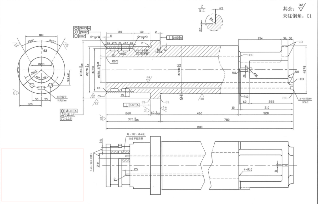
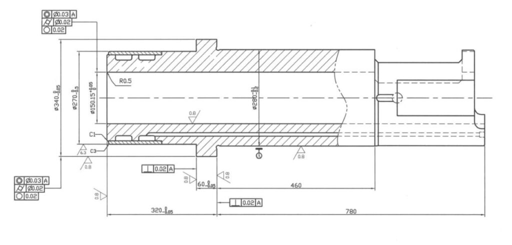
Specification: 2500T-Φ340*Φ150*1100 Shot Sleeve
Shot Sleeve material is DAC
Production technical requirement: Forging – annealing- roughing-Quenching-Tempering -finishing -Surface nitrogen
Lifespan warranty 30K-50K molding under normal conditions
Heat-treatment is HRC45-50
Surface nitrogen is HV850 and above
The thickness of the surface nitride layer is 0.25-0.35mm
The cooling channel at D is pressurized with 0.5MPA water pressure for 24 hours, and there is no leakage at D at the weld
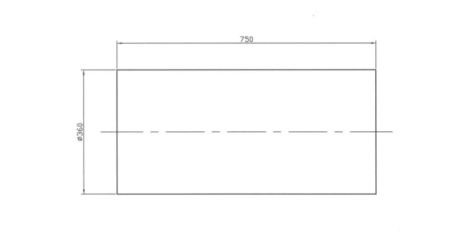
1. Cutting pipe material
Machining Equipment: Sawing machine
Machining Knives:Saw blade
Measuring tool:0-500mm Vernier caliper/1M steel ruler
Processing steps
- Place the DAC bar of Φ360 on the bed (note that the axis of the raw material is parallel to the saw table), and start sawing with a length of 750mm (ensure that the sawing section is perpendicular to the material axis)
- Check the length and size of the cutting size
2. Cutting Sleeve Material
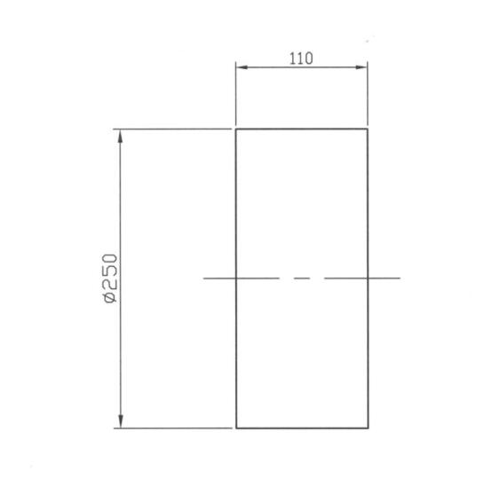
Machining Equipment: Sawing machine
Machining Knives:Saw blade
Measuring tool:0-300mm Vernier caliper/0.5M steel ruler
Processing steps
- Place the #45 bar of Φ250 on the bed (note that the axis of the raw material is parallel to the saw table), and start sawing with a length of 110mm (ensure that the sawing section is perpendicular to the material axis)
- Check the length and size of the cutting size
3. Forged material tube blank
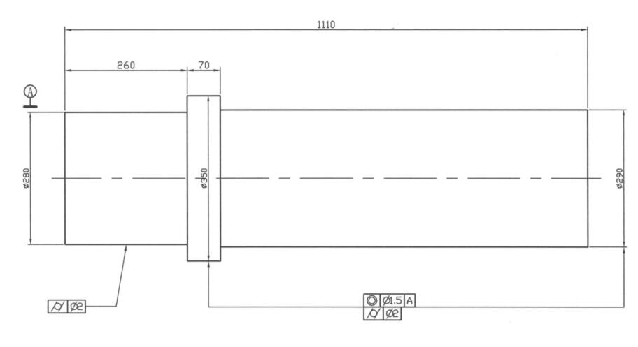
Machining Equipment: Forging hydraulic press
Machining Knives:Forging hammer
Measuring tool:0-500mm Vernier caliper/1.5M steel ruler/Flaw detector
Processing steps:
- Burn the workpiece red, place it on the platform of the forging hydraulic press for free forging, and forge according to the drawing size
- After forging, the workpiece is tempered to eliminate internal stress
- Flaw detection
4. Forged Sleeve blank
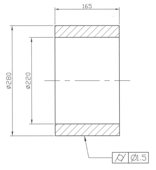
Machining Equipment: Forging hydraulic press
Machining Knives:Forging hammer
Measuring tool:0-300mm Vernier caliper/Flaw detector
Processing steps:
- Burn the workpiece red, place it on the platform of the forging hydraulic press for free forging, and forge according to the drawing size
- After forging, the workpiece is tempered to eliminate internal stress
- Flaw detection
5. Rough turning Sleeve
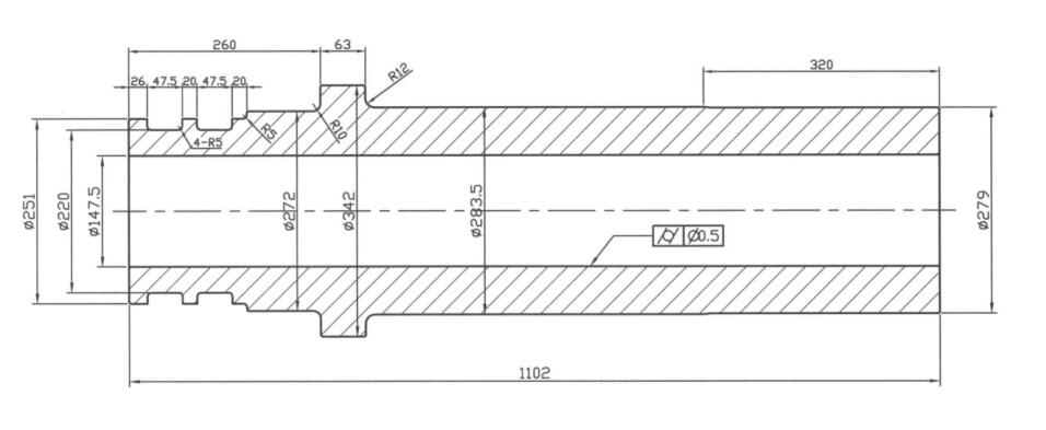
Machining Equipment: CW6180 Ordinary lathe
Machining Knives:45 ˚ Face turning tool/45 ˚ Positive turning tool/Grooving knife /90˚ Inner hole cutter/ Φ35&Φ75 Drill
Measuring tool:0-300mm Vernier caliper / 0-500 Vernier Caliper / 1.5M ruler /125-150/200-225/225-275/275-300/300-400 Outside micrometer
Processing steps:
- Clamp the left end of the workpiece with a self-centering three-jaw, correct it, and punch a center hole 3.15/6.7
- The center of the right end pushes the workpiece, and the left end part of the workpiece is rough machined according to the size shown in the figure with the spindle 100R/M, 0.15mm feed amount
- U-turn, clamp the right end of the workpiece, correct it, and punch the center hole A3.15/6.7; rough machine the left end of the workpiece according to the size shown in the figure
- The center support supports the Φ282 size section close to Φ342, and the end face of the workpiece is turned. Then use a Φ35 drill to drill a hole to a depth of 600mm, and then use a Φ75 drill to ream the hole
- U-turn, clamp the left end of the workpiece with a section of the center frame to hold it, use Φ35 and Φ75 drill bits to drill the inner hole of the workpiece respectively
- Then rough turning the inner hole to 600mm with spindle 80r/m and 0.12m feed
- U-turn, the center frame supports the workpiece, the other end of the rough turning internal control to the workpiece receiving tool
- All sizes are left with a margin of 2-2.5mm for fine turning and fine grinding
6. Drill Deep Holes
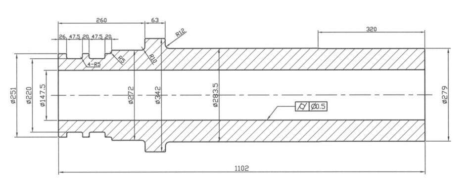
Machining Equipment: GD6010 Deep hole drilling machine
Machining Knives:Φ15*1200 deep drilling head, RC1/2 taptool
Measuring tool: 0-150mm vernier caliper / Rc1/2 thread gauge / Φ14*1050 detection rod, visual inspection
Processing steps:
- Place the workpiece flat on the water platform of the deep hole drilling machine, and drill the 2-Φ15 cooling water with a depth of 980mm with a spindle of 60r/m and a feed rate of 0.25mm.
- Tapping 2-Rc1/2
- Insert the Φ14*1050 detection rod into the deep hole to the sink position to ensure that the deep hole has been drilled
7. Heat treatment
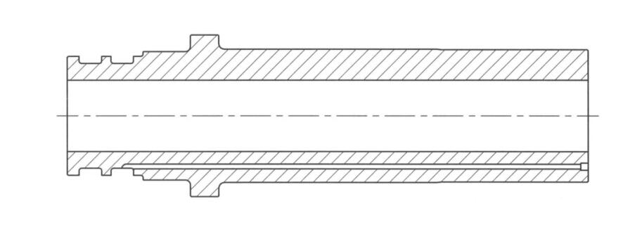
Machining Equipment: Vacuum furnace
Measuring tools: portable Rockwell hardness tester, metallographic analyzer, visual inspection
Processing steps:
- Place the workpiece in a vacuum furnace for vacuum quenching heat treatment: HRC45-50
- After the workpiece is released and cooled, use a portable Rockwell hardness tester to measure the heat treatment hardness of the workpiece
- Metallographic analysis
8. Fine Turning Tube Position
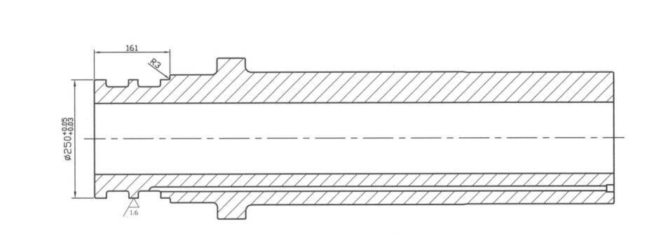
Machining Equipment: CW6180B Ordinary lathe
Machining Knives:45˚ face turning tool/45˚ positive turning tool
Measuring tool:0-300 vernier caliper /250-275mm outer diameter micrometer
Processing steps:Clamp the right end of the workpiece with a four-jaw chuck for correction, and the center of the right end + taper plug on the workpiece, with the spindle 65r/m, 0.1mm feed rate for precision turning and water jacket machining according to the size shown in the figure
9. Fine Turning Tube
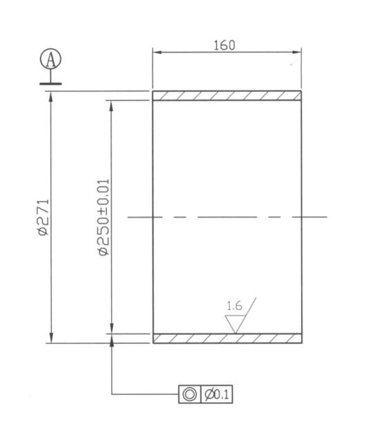
Machining Equipment: CW6180B Ordinary lathe
Machining Knives:45˚ face turning tool/45˚ positive turning tool/90 ˚Inner hole turning tool
Measuring tool:0-300 vernier caliper /250-275mm outer diameter micrometer/150-300mm inner diameter dial indicator
Processing steps:
- Support the inner hole of the left end of the workpiece with self-centering three claws, correct it, the center of the right end + taper plug the workpiece, the right end surface and outer circle are semi-finished with the spindle 90r/m and 0.12mm feed rate according to the size shown in the figure
- Clamp the outer circle of the right end of the workpiece, correct it, and machine the other end surface and inner hole according to the size shown in the figure.
- The outer circle size reserved 1mm is used for fine turning and fine grinding, and the inner hole size is matched with the sleeve tube position
10. Welding
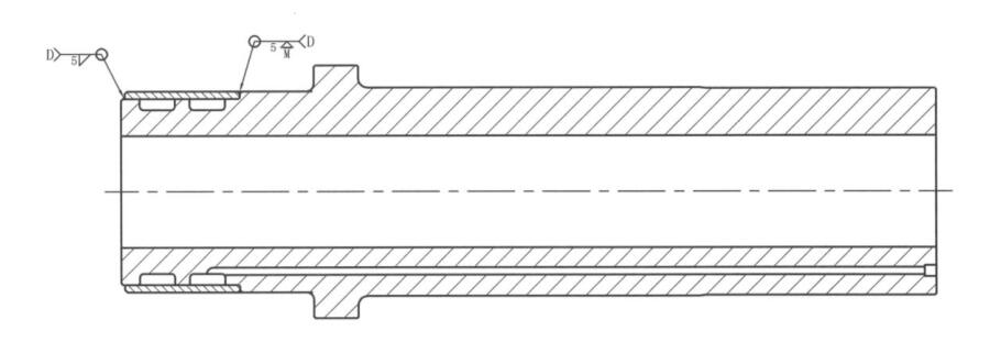
Machining Equipment: WSM315Argon arc welding machine
Machining Knives:DAC imported ace welding machine
Measuring tool:High pressure water test, visual inspection
Processing steps:
- Heat the workpiece locally to 200-300˚C before welding
- Then use the argon arc welding rod to melt the bottom end of the workpiece to be welded at a high temperature, and then use the welding rod to fill the welding part (note that the welding is firm, without pores, trachoma and other defects)
- Annealing, stress-relieving treatment for welding parts
11. Fine Turning
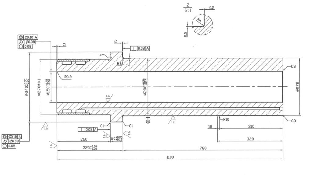
Machining Equipment: CW6180B Ordinary lathe
Machining Knives:45˚ face turning tool/45˚ positive turning tool/90 ˚Inner hole turning tool
Measuring tool:0-300mm Vernier caliper / 0-500 Vernier Caliper / 1.5M ruler /125-150/200-225/225-275/275-300/300-400 Outside micrometer/Φ50-160 Inner diameter dial indicator
Processing steps:
- Use the four-jaw chuck to calibrate the left end of the workpiece, the center of the right end + the taper plug to top the workpiece, and the feed rate of the spindle 80r/m, 0.1mm to finish turning the outer circle of the right end of the barrel according to the size shown in the drawing.
- The right end of the workpiece is replaced with a center support product, and the right end surface and inner hole of the precision turning (depth ≥600mm)
- U-turn, clamp the right end of the workpiece, correct it, the center of the right end + taper plug the workpiece, with the spindle 80r/m, 0.1mm of the end tool, according to the size of the figure to finish turning the outer circle of the left end of the barrel
- The right end of the workpiece is replaced with a center support product, and the left end and inner hole of the workpiece are finely turned (note that the inner hole must be smoothly connected to the tool mark)
- There are tolerance dimensions with a margin of 0.30-0.35mm for fine grinding, and the remaining dimensions are finished in place
12. Rough grinding of the inner hole
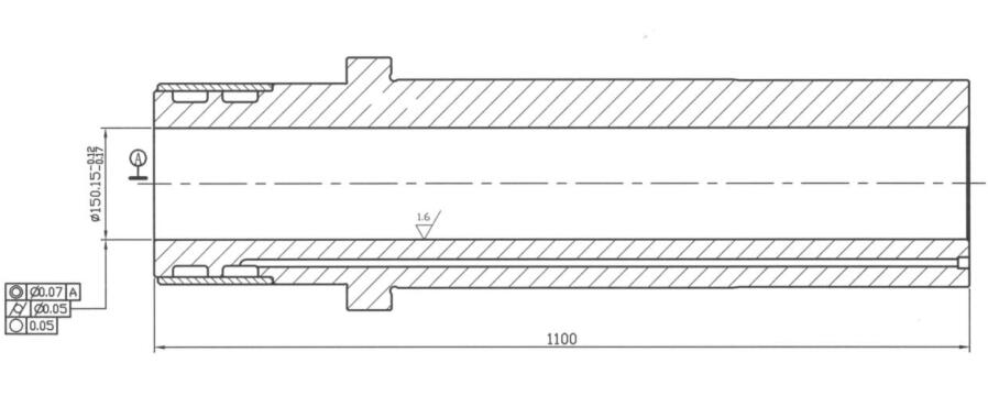
Machining Equipment: CW6180B Ordinary lathe +Dedicated grinding rod
Machining Knives:Φ100 Dedicated grinding rod / Φ80,Φ100 Grinding wheel
Measuring tool:125-150/150-175 Outside micrometer/100-200 Inner diameter dial indicator
Processing steps:
- Clamp the right end of the workpiece with a self-centering three-jaw, with a center support to hold the workpiece and correct it
- Roughly grinding the inner hole with a spindle of 1800r/m and a feed rate of 0.1mm
- Ensure all dimensional tolerances, form and position tolerances and roughness requirements
13. Fine grinding inner hole

Machining Equipment: HM0016 Deep hole grinder
Machining Knives:Φ150-Φ175 Grinding head and tooling
Measuring tool:125-150/150-175 Outside micrometer/100-200 Inner diameter dial indicator
Processing steps:
- Place the right end surface of the workpiece vertically on the horizontal clamping table of the deep hole grinder, and correct it so that the inner hole of the workpiece and the grinding head are on the same axis line
- Deep hole precision grinding inner hole processing with spindle 30r/m and 0.002mm feed
- Ensure all dimensional tolerances, form and position tolerances and roughness requirements
14. Grind the outer circle
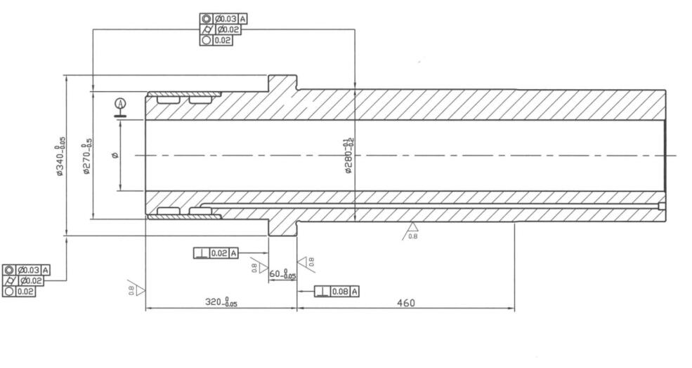
Machining Equipment: M1432B*1500 Universal Cylindrical Grinding Machine
Machining Knives:Grinding wheel, dial, center top, Φ150 special tooling spindle
Measuring tool:50-75, 250-275, 275-300, 300-400mm outside micrometer, 0-300mm depth gauge
Processing steps:
- The right end of the workpiece is machined with “chicken clip + dial with special tooling mandrel”, and the special tooling mandrel for the center of the right end of the grinder (the left end of the product) is used for correction. External machining of grinding workpieces
- Ensure all dimensional tolerances, form and position tolerances and roughness requirements
15. Milling mouth
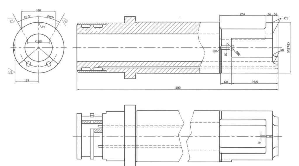
Machining Equipment: XJ6325A Rocker arm universal milling
Machining Knives:Φ8 spherical milling cutters, Φ16/Φ20/Φ30/Φ40 three-blade milling cutters, 100 face milling cutters and V-shaped horizontal block + special tooling
Measuring tool:
0-300mm vernier caliper
0-320˚Universal Angle Ruler
Processing steps:
- Position the workpiece on the V-shaped horizontal block and correct it; rotate the spindle head of the universal milling machine by 29.5˚, and use the spindle 90r/m, 0.12mm feed rate for finishing milling material opening processing
- Position the workpiece on the V-shaped horizontal block and correct it; rotate the spindle head of the universal milling machine by 29.5˚, and use the spindle 90r/m, 0.12mm feed rate for finishing milling material opening processing
- Position the milling machine spindle head and correct it, rotate the workpiece 90˚ clockwise, use a Φ100 end milling cutter, and finish milling the flat position of the material tube with the spindle 120r/s and the feed rate of 0.12mm
16 Nitriding
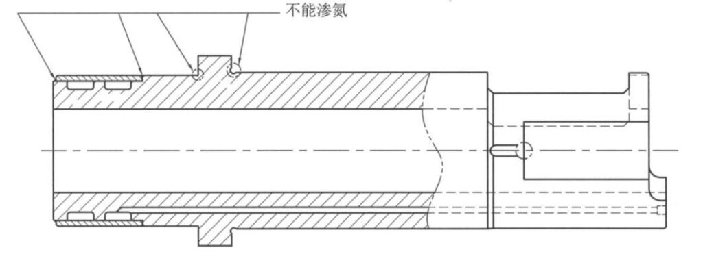
Machining Equipment: Nitriding furnace
Machining Knives:Nitrogen
Measuring tool:Rockwell hardness tester, visual inspection
Processing steps:
- Place the workpiece in the nitriding furnace for nitriding treatment
- Pay attention to the welding parts and corners (in the picture) coated with anti-nitrogen agent, and do a good job of anti-nitrogen treatment
17. Inspection, packaging
Machining Equipment: Packaging box
Machining Knives:Packaging film, anti-rust oil
Measuring tool:0-300mm/0-500mm vernier calipers, 50-75mm/150-175mm/250-275mm/275-300mm/300-400mm outside micrometer, 50-160mm inside diameter dial indicator, 0-300mm depth gauge, V-shaped horizontal block + Dial indicator
